Batteries may be advertised as Long Life, High Capacity, High Energy, Deep Cycle, Heavy Duty, Fast Charge, Quick Charge, Ultra and other, ill defined, parameters and there are few industry or legal standards defining exactly what each of these terms means. Advertising words can mean whatever the seller wants them to mean. Apart from the basic battery design, performance actually depends on how the batteries are used and also on the environmental conditions under which they are used, but these conditions are rarely, if ever, specified in mass market advertising. For the consumer this can be very confusing or misleading. The battery industry itself however does not use such vague terms to specify battery performance and specifications normally include a statement defining or limiting the operating or environmental conditions within which the claimed performance can be delivered.
The following section outlines key parameters used to characterise the cells or batteries and shows how these parameters may vary with the operating conditions.
Energy cells have been developed for a wide range of applications using a variety of different technologies, resulting in a wide range of available performance characteristics. The graphs below show some of the main factors an applications engineer should take into account when specifying a battery to match the performance requirements of the end product.
The nominal voltage of a galvanic cell is fixed by the electrochemical characteristics of the active chemicals used in the cell, the so called cell chemistry. The actual voltage appearing at the terminals at any particular time, as with any cell, depends on the load current and the internal impedance of the cell and this varies with, temperature, the state of charge and with the age of the cell.
The graph below shows typical discharge discharge curves for cells using a range of cell chemistries when discharged at 0.2C rate. Note that each cell chemistry has its own characteristic nominal voltage and discharge curve. Some chemistries such as Lithium Ion have a fairly flat discharge curve while others such as Lead acid have a pronounced slope.
The power delivered by cells with a sloping discharge curve falls progressively throughout the discharge cycle. This could give rise to problems for high power applications towards the end of the cycle. For low power applications which need a stable supply voltage, it may be necessary to incorporate a voltage regulator if the slope is too steep. This is not usually an option for high power applications since the losses in the regulator would rob even more power from the battery.
A flat discharge curve simplifies the design of the application in which the battery is used since the supply voltage stays reasonably constant throughout the discharge cycle. A sloping curve facilitates the estimation of the State of Charge of the battery since the cell voltage can be used as a measure of the remaining charge in the cell. Modern Lithium Ion cells have a very flat discharge curve and other methods must be used to determine the State of Charge

The X axis shows the cell characteristics normalised as a percentage of cell capacity so that the shape of the graph can be shown independent of the actual cell capacity. If the X axis was based on discharge time, the length of each discharge curve would be proportional to the nominal capacity of the cell.
Cell performance can change dramatically with temperature. At the lower extreme, in batteries with aqueous electrolytes, the electrolyte itself may freeze setting a lower limit on the operating temperature. At low temperatures Lithium batteries suffer from Lithium plating of the anode causing a permanent reduction in capacity. At the upper extreme the active chemicals may break down destroying the battery. In between these limits the cell performance generally improves with temperature. See also Thermal Management and Battery Life for more details.

The above graph shows how the performance of Lithium Ion batteries deteriorates as the operating temperature decreases.
Probably more important is that, for both high and low temperatures, the further the operating temperature is from room temperature the more the cycle life is degraded. See Lithium Battery Failures.
The self discharge rate is a measure of how quickly a cell will lose its energy while sitting on the shelf due to unwanted chemical actions within the cell. The rate depends on the cell chemistry and the temperature.
Cell Chemistry
The following shows the typical shelf life for some primary cells:
Typical self discharge rates for common rechargeable cells are as follows:
Temperature Effects
The rate of unwanted chemical reactions which cause internal current leakage between the positive and negative electrodes of the cell, like all chemical reactions, increases with temperature thus increasing the battery self discharge rate. See also Battery Life . The graph below shows typical self discharge rates for a Lithium Ion battery.

The internal impedance of a cell determines its current carrying capability. A low internal resistance allows high currents.
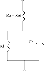
Battery Equivalent Circuit
The diagram on the right shows the equivalent circuit for an energy cell.
Typical internal resistance is in the order of milliohms.
When current flows through the cell there is an IR voltage drop across the internal resistance of the cell which decreases the terminal voltage of the cell during discharge and increases the voltage needed to charge the cell thus reducing its effective capacity as well as decreasing its charge/discharge efficiency. Higher discharge rates give rise to higher internal voltage drops which explains the lower voltage discharge curves at high C rates. See "Discharge Rates" below.
The internal impedance is affected by the physical characteristics of the electrolyte, the smaller the granular size of the electrolyte material the lower the impedance. The grain size is controlled by the cell manufacturer in a milling process.
Spiral construction of the electrodes is often used to maximise the surface area and thus reduce internal impedance. This reduces heat generation and permits faster charge and discharge rates.
The internal resistance of a galvanic cell is temperature dependent, decreasing as the temperature rises due to the increase in electron mobility. The graph below is a typical example.

Thus the cell may be very inefficient at low temperatures but the efficiency improves at higher temperatures due to the lower internal impedance, but also to the increased rate of the chemical reactions. However the lower internal resistance unfortunately also causes the self discharge rate to increase. Furthermore, cycle life deteriorates at high temperatures. Some form of heating and cooling may be required to maintain the cell within a restricted temperature range to achieve the optimum performance in high power applications.
The internal resistance of most cell chemistries also tends to increase significantly towards the end of the discharge cycle as the active chemicals are converted to their discharged state and hence are effectively used up. This is principally responsible for the rapid drop off in cell voltage at the end of the discharge cycle.
In addition the Joule heating effect of the I2R losses in the internal resistance of the cell will cause the temperature of the cell to rise.
The voltage drop and the I2R losses may not be significant for a 1000 mAh cell powering a mobile phone but for a 100 cell 200 Ah automotive battery they can be substantial. Typical internal resistance for a 1000mA Lithium mobile phone battery is around 100 to 200mOhm and around 1mOhm for a 200Ah Lithium cell used in an automotive battery. See example.
Operating at the C rate the voltage drop per cell will be about 0.2 volts in both cases, (slightly less for the mobile phone). The I2R loss in the mobile phone will be between 0.1 and 0.2 Watts. In the automotive battery however the voltage drop across the whole battery will be 20 Volts and I2R power loss dissipated as heat within the battery will be 40 Watts per cell or 4KW for the whole battery. This is in addition to the heat generated by the electrochemical reactions in the cells.
As a cell ages, the resistance of the electrolyte tends to increase. Aging also causes the surface of the electrodes to deteriorate and the contact resistance builds up and at the same the effective area of the plates decreases reducing its capacitance. All of these effects increase the internal impedance of the cell adversely affecting its ability to perform. Comparing the actual impedance of a cell with its impedance when it was new can be used to give a measure or representation of the age of a cell or its effective capacity. Such measurements are much more convenient than actually discharging the cell and can be taken without destroying the cell under test. See "Impedance and Conductance Testing"
The internal resistance also influences the effective capacity of a cell. The higher the internal resistance, the higher the losses while charging and discharging, especially at higher currents. This means that for high discharge rates the lower the available capacity of the cell. Conversely, if it is discharged over a prolonged period, the AmpHour capacity is higher. This is important because some manufacturers specify the capacity of their batteries at very low discharge rates which makes them look a lot better than they really are.
The discharge curves for a Lithium Ion cell below show that the effective capacity of the cell is reduced if the cell is discharged at very high rates (or conversely increased with low discharge rates). This is called the capacity offset and the effect is common to most cell chemistries.

Battery Load
Battery discharge performance depends on the load the battery has to supply.
If the discharge takes place over a long period of several hours as with some high rate applications such as electric vehicles, the effective capacity of the battery can be as much as double the specified capacity at the C rate. This can be most important when dimensioning an expensive battery for high power use. The capacity of low power, consumer electronics batteries is normally specified for discharge at the C rate whereas the SAE uses the discharge over a period of 20 hours (0.05C) as the standard condition for measuring the Amphour capacity of automotive batteries. The graph below shows that the effective capacity of a deep discharge lead acid battery is almost doubled as the discharge rate is reduced from 1.0C to 0.05C. For discharge times less than one hour (High C rates) the effective capacity falls off dramatically.
The effectiveness of charging is similarly influenced by the rate of charge. An explanation of the reasons for this is given in the section on Charging Times .
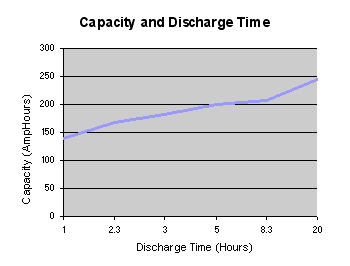
There are two conclusions to be drawn from this graph:
Duty Cycle
Duty cycles are different for each application. EV and HEV appications impose particular, variable loads on the battery. See Load Testing example. Stationary batteries used in distributed grid energy storage applications may have very large SOC changes and many cycles per day.
It is important to know how much energy is used per cycle and to design for the maximum energy throughput and power delivery, not the average.
Notes: For information
The Peukert equation is a convenient way of characterising cell behaviour and of quantifying the capacity offset in mathematical terms.
This is an empirical formula which approximates how the available capacity of a battery changes according to the rate of discharge. C = I n T where "C" is the theoretical capacity of the battery expressed in amp hours, "I" is the current, "T" is time, and "n" is the Peukert Number, a constant for the given battery. The equation shows that at higher currents, there is less available energy in the battery. The Peukert Number is directly related to the internal resistance of the battery. Higher currents mean more losses and less available capacity.
The value of the Peukert number indicates how well a battery performs under continuous heavy currents. A value close to 1 indicates that the battery performs well; the higher the number, the more capacity is lost when the battery is discharged at high currents. The Peukert number of a battery is determined empirically. For Lead acid batteries the number is typically between 1.3 and 1.4
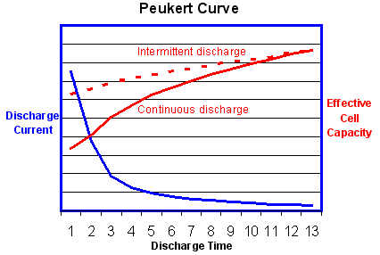
The graph above shows that the effective battery capacity is reduced at very high continuous discharge rates. However with intermittent use the battery has time to recover during quiescent periods when the temperature will also return towards the ambient level. Because of this potential for recovery, the capacity reduction is less and the operating efficiency is greater if the battery is used intermittently as shown by the dotted line.
This is the reverse of the behaviour of an internal combustion engine which operates most efficiently with continuous steady loads. In this respect electric power is a better solution for delivery vehicles which are subject to continuous interruptions.
The Ragone plot is useful for characterising the trade-off between effective capacity and power handling. Note that the Ragone plots are usually based on logarithmic scales.
The graph below shows the superior gravimetric energy density of Lithium Ion cells. Note also that Lithium ion cells with Lithium Titanate anodes (Altairnano) deliver a very high power density but a ruduced energy density.
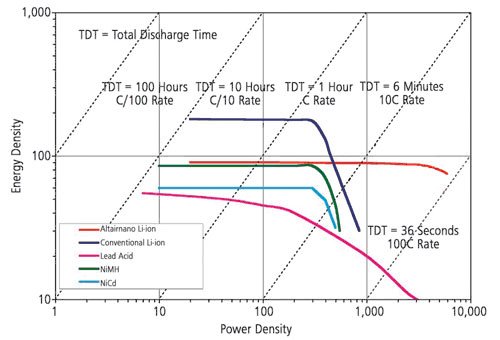
Source Altairnano
The Ragone plot below compares the performance of a range of electrochemical devices. It shows that ultracapacitors (supercapacitors) can deliver very high power but the storage capacity is very limited. On the other hand Fuel Cells can store large amounts of energy but have a relatively low power output.

The sloping lines on the Ragone plots indicate the relative time to get the charge in or out of the device. At one extreme, power can be pumped into, or extracted from, capacitors in microseconds. This makes them ideal for capturing regenerative braking energy in EV applications. At the other extreme, fuel cells have a very poor dynamic performance taking hours to generate and deliver their energy. This limits their application in EV applications where they are often used in conjunction with batteries or capacitors to overcome this problem. Lithium batteries are somewhere in between and provide a reasonable compromise between the two.
See also Alternative Energy Storage Comparisons.
The ability to deliver high current pulses is a requirement of many batteries. The current carrying capacity of a cell depends on the effective surface area of the electrodes. (See Energy/Power Trade-Offs). The current limit is however set by the rate at which the chemical reactions occur within the cell. The chemical reaction or "charge transfer" takes place on the surface of the electrodes and the initial rate can be quite high as the chemicals close to the electrodes are transformed. Once this has occurred however, the reaction rate becomes limited by the rate at which the active chemicals on the electrode surface can be replenished by diffusion through the electrolyte in a process known as "mass transfer". The same principle applies to the charging process and is explained in more detail in the section on Charging Times. The pulse current can therefore be substantially higher than the C rate which characterises the continuous current performance.
This is one of the key cell performance parameters and gives an indication of the expected working lifetime of the cell.
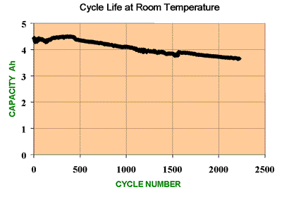
The cycle life is defined as the number of cycles a cell can perform before its capacity drops to 80% of its initial specified capacity.
Each charge - discharge cycle, and the associated transformation cycle of the active chemicals it brings about, is accompanied by a slow deterioration of the chemicals in the cell which will be almost imperceptible to the user. This deterioration may be the result of unavoidable, unwanted chemical actions in the cell or crystal or dendrite growth changing the morphology of the particles making up the electrodes. Both of these events may have the effect of reducing the volume of the active chemicals in the cell, and hence its capacity, or of increasing the cell's internal impedance.
Note that the cell does not die suddenly at the end of the specified cycle life but continues its slow deterioration so that it continues to function normally except that its capacity will be significantly less than it was when it was new.
The cycle life as defined is a useful way of comparing batteries under controlled conditions, however it may not give the best indication of battery life under actual operating conditions. Cells are seldom operated under successive, complete charge - discharge cycles, they are much more likely to be subject to partial discharges of varying depth before complete recharging. Since smaller amounts of energy are involved in partial discharges, the battery can sustain a much greater number of shallow cycles. Such usage cycles are typical for Hybrid Electric Vehicle applications with regenerative braking. See how cycle life varies with depth of discharge (DOD) in Battery Life.
Cycle life also depends on temperature, both operating and storage temperature. See more details in the section on Lithium Battery Failures.
A more representative measure of battery life is the Lifetime Energy Throughput. This is the total amount of energy in Watthours which can be put into and taken out of a battery over all the cycles in its lifetime before its capacity reduces to 80% of its initial capacity when new. It depends on the cell chemistry and the operating conditions. Unfortunately this measure is not yet in common use by cell manufacturers and has not yet been adopted as a battery industry standard. Until it comes into general use it will not be possible to use it to compare the performance of cells from different manufacturers in this way but, when available, at least it provides a more useful guide to applications engineers for estimating the useful life of batteries used in their designs.
See also State of Health (SOH) and Estimating Battery Lifetimes
Cycle life decreases with increased Depth of Discharge (DOD) (See Battery Life) and many cell chemistries will not tolerate deep discharge and cells may be permanently damaged if fully discharged. Special cell constructions and chemical mixes are required to maximise the potential DOD of deep cycle batteries.
Charging curves and recommended charging methods are included in a separate section on Charging